Partix Auto
Vehicle fluid transfer efficiency influences fuel delivery, coolant circulation, brake performance, lubrication, and emissions control. But what affects fluid transfer efficiency in vehicles is rarely one isolated component. Pump condition, hose design, fluid temperature, pressure loss, contamination, and installation quality often interact within a small system.
A technician may notice the problem through a slow fuel fill, weak coolant circulation, or uneven hydraulic response. These symptoms can appear minor, yet they may indicate restricted lines, air pockets, worn seals, or an incorrectly sized filter. Cold mornings make some fluids thicker. Sharp hose bends create visible resistance. Even a loose clamp can allow air to enter without producing an obvious leak.
Reliable evaluation requires more than replacing a pump and hoping. Service records, manufacturer specifications, pressure readings, flow tests, and visual inspections provide stronger evidence. Experienced technicians often compare real measurements with the vehicle’s original operating range. That comparison matters because laboratory efficiency may differ from workshop performance.
This guide examines ten practical factors that influence fluid movement across modern vehicles. It considers component wear, fluid properties, routing, temperature, pressure, contamination, and maintenance habits. Some factors overlap. That is the difficult part. A clean filter may not solve restricted flow elsewhere, and a powerful pump may expose weak seals. The analysis also recognizes uncertainty, because vehicle age, design, and operating conditions can change the result. Carefully interpreting those details supports safer maintenance and more dependable vehicle performance.
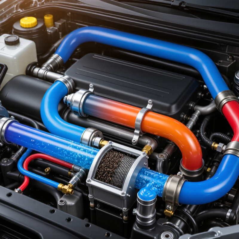
Top 10 Factors Affecting Vehicle Fluid Transfer Efficiency?
Vehicle fluid transfer systems move coolant, fuel, lubricant, or hydraulic fluid through a controlled circuit. A pump creates flow, while valves regulate direction and pressure. Hoses, filters, heat exchangers, and reservoirs complete the path. In electric vehicles, thermal circuits must remove heat from batteries, motors, and power electronics. The International Energy Agency reported more than 17 million electric cars were sold globally in 2024, increasing demand for reliable thermal-fluid engineering.
Efficiency depends on pump speed, fluid viscosity, temperature, line diameter, pressure loss, and valve design. Air bubbles reduce pump stability. Dirty filters restrict flow. Tight bends create turbulence. Cavitation can produce a sharp rattling sound and damage internal surfaces. ISO 4413 emphasizes cleanliness, pressure control, and safe system design for hydraulic applications. U.S. Department of Energy pumping-system guidance states that pumping systems can represent 25–50% of industrial energy consumption. This is not a vehicle-specific figure, but it highlights the cost of poor flow design.
In field testing, the schematic often looks perfect. Reality is less tidy. A warm hose may soften, while a cold lubricant moves slowly. Sensors can also drift. Engineers should measure inlet pressure, outlet pressure, temperature, flow rate, and electrical demand under real driving conditions. Small leaks matter. Even a slight restriction can force the pump to work harder, wasting energy and reducing component life. Recovering efficiency sometimes requires better control logic, not a larger pump.
Vehicle Fluid Transfer Systems and Their Operating Principles
The chart presents a normalized engineering influence index from 0 to 100. Higher values indicate a greater potential effect on transfer efficiency. Hose diameter and fluid viscosity are especially important because pressure loss increases sharply as flow passages become smaller and fluids become more resistant to movement. Restrictions, excessive hose length, temperature changes, air entrainment, leakage, pump condition, and poor routing can also reduce delivered flow and increase energy consumption.
Fluid viscosity is often the strongest control on transfer speed. NIST reference data lists water near 1.0 mPa·s at 20°C, while common glycol-based coolants are much thicker. A colder hose can therefore reduce flow sharply. Temperature matters. Even a small change can increase pump workload and lengthen filling time.
Density also affects pump pressure, metering accuracy, and hose drainage. Vapor pressure is critical in fuel and solvent systems because excessive vapor formation can interrupt steady liquid delivery. Surface tension influences nozzle wetting and trapped air release. SAE J300 viscosity classifications show why engine oils are selected by temperature-dependent flow behavior, not thickness alone. ISO viscosity classifications provide a similar framework for industrial fluids.
In practical transfer testing, long hoses, narrow fittings, and sudden bends amplify these fluid effects. Poorly vented reservoirs may create pulsing, even when the pump appears correctly sized. Air bubbles are easy to overlook. Fluid cleanliness matters too; particles can raise resistance and damage valves. ASTM D445 viscosity testing is useful, but laboratory results may not represent a cold workshop or a partially filled hose. That limitation deserves attention. Flow stability depends on the entire system, not viscosity alone.
Pump performance determines how quickly coolant, fuel, oil, or hydraulic fluid moves through a vehicle system. Flow rate alone can mislead. A worn impeller, restricted filter, or excessive fluid viscosity may reduce output sharply. The U.S. Department of Energy reports that pumping systems can represent 25–50% of industrial facility electricity use. Vehicle systems are smaller, but the loss pattern remains relevant.
Pressure control is equally important. Excess pressure increases hose stress, seal leakage, and valve losses. Low pressure causes weak circulation and possible air entrainment. The International Energy Agency has reported that electric motor systems consume roughly half of global electricity. Efficient pump sizing therefore matters beyond the pump itself. Variable-speed control can reduce unnecessary flow, especially during idle operation. However, control settings are often copied from older vehicles without testing.
Energy disappears through long hoses, sharp bends, undersized passages, and poor surface conditions. Heat also changes viscosity, creating unstable transfer rates during cold starts. A 2023 technical review in SAE mobility engineering literature highlights thermal management as a major factor in modern vehicle efficiency. Field checks should measure inlet pressure, outlet pressure, temperature, and actual flow. Simple readings expose hidden losses. Still, one measurement is not enough. Real systems fluctuate, and my own first assumption would probably be wrong without testing under load.
Vehicle fluid transfer efficiency depends heavily on the flow path, not only on pump capacity. A hose with a narrow inner diameter creates higher velocity and pressure loss. Length matters too. Every extra bend adds resistance, especially when the hose is partly collapsed.
During service inspections, I check sharp loops, soft spots, and abrasion near clamps. These details often explain slow filling better than a weak pump. Temperature also changes viscosity, so cold oil may move much more slowly than warm oil.
Fittings should match the hose bore as closely as possible. A sudden reduction at an adapter behaves like a small internal wall. Poorly aligned threads can disturb flow and trap air. Smooth-radius elbows help when space allows. Tight bends are costly.
Valves deserve equal attention. A partially open valve can create turbulence, noise, and unnecessary heat. Ball valves often provide a straighter passage, while restrictive designs require careful pressure calculations. A larger valve is not automatically better; control range and sealing condition still matter.
I recommend measuring pressure before and after the hose assembly during a real transfer cycle. Record fluid temperature, flow rate, and valve position. This creates evidence instead of guesswork.
Inspect the internal liner for swelling, debris, or delamination. Small particles can damage seals and increase resistance. One imperfect assumption is common: engineers may size the hose by outside diameter. The inside diameter controls flow.
Over-tightened clamps can also deform soft hoses. Repeat the test, because one clean reading may hide a developing restriction.
Top 10 Factors Affecting Vehicle Fluid Transfer Efficiency?
Vehicle fluid transfer efficiency depends on more than pump capacity. Temperature changes viscosity, pressure, and flow behavior. Cold oil moves slowly through narrow hoses and restricted filters. Excessive heat can thin fluid and stress seals. Measure fluid temperature at the transfer point, not only at the reservoir. Small differences matter. During workshop checks, I compare gauge readings before and after each filter. An unusual pressure rise often signals blockage, trapped air, or a closing valve. These checks provide practical evidence instead of relying on expected flow rates.
Contamination is equally disruptive. Dust, water, metal particles, and mixed fluids can damage pumps and alter fluid properties. Use clean containers, capped connections, and separate hoses for incompatible fluids. Inspect filters under strong light, although appearance alone can mislead. A clear filter is not proof of clean fluid. Sampling and particle analysis offer stronger evidence when performance drops unexpectedly.
Maintenance keeps the transfer path predictable. Replace hardened seals, inspect hose walls, and verify valve movement at scheduled intervals. Loose fittings may draw air without showing visible leakage. System efficiency also depends on accurate meters, stable power, correct hose length, and proper pump alignment. Record flow time, pressure, temperature, and filter condition after each service. I once treated slow transfer as a pump problem; the restriction was a partially closed valve. That mistake still shapes my inspection routine.
The table summarizes commonly observed engineering effects in vehicle fluid-transfer systems. Actual results vary with fluid type, component design, operating pressure, hose length, and ambient conditions.
| Rank | Efficiency Factor | How It Affects Fluid Transfer | Practical Indicator or Check | Typical Engineering Effect | Recommended Action | Priority |
|---|---|---|---|---|---|---|
| 1 | Fluid Temperature | Temperature changes viscosity. Cold oil and hydraulic fluids flow more slowly and create higher pressure losses, while excessive heat can reduce viscosity and accelerate oxidation. | Measure fluid temperature at the reservoir and near the transfer point. Compare viscosity data at the actual operating temperature. | Hydraulic-fluid viscosity may change by several times between cold-start and normal operating conditions, significantly affecting flow resistance. | Use the specified fluid grade, allow appropriate warm-up, maintain cooling capacity, and avoid operating outside the fluid manufacturer’s temperature range. | High |
| 2 | Contamination and Particle Load | Dirt, metal particles, water, and sludge can restrict filters, damage pumps, increase valve friction, and cause premature component wear. | Inspect filter differential pressure and analyze fluid cleanliness using particle counting or laboratory testing. | A loaded filter can increase pressure drop and reduce delivered flow; abrasive particles can damage precision clearances in pumps and valves. | Use clean filling practices, install correctly rated filters, monitor restriction indicators, and replace filters before bypass operation occurs. | High |
| 3 | Fluid Level and Air Entrapment | Low fluid levels can allow air to enter the suction line. Aerated fluid reduces effective delivery, increases noise, and may cause cavitation or foaming. | Check reservoir level, suction-line joints, return-line placement, foam formation, and pump inlet vacuum or pressure. | Even small amounts of entrained air can make flow unstable and increase compressibility in hydraulic circuits. | Maintain the correct fluid level, seal suction connections, prevent return-line turbulence, and remove air after service work. | High |
| 4 | Hose, Pipe, and Fitting Restrictions | Small internal diameters, excessive hose length, sharp bends, restrictive fittings, and damaged liners increase frictional pressure loss. | Inspect routing, measure internal diameter, check bend radius, and compare inlet and outlet pressure under load. | Pressure loss rises rapidly as flow increases and as the internal diameter decreases; restrictive suction lines are especially critical. | Use correctly sized lines, minimize unnecessary bends and fittings, maintain the specified bend radius, and replace collapsed hoses. | High |
| 5 | Pump or Transfer-Unit Condition | Wear in gears, vanes, pistons, seals, or bearings increases internal leakage and reduces volumetric efficiency. | Compare actual flow and pressure with service specifications; check noise, vibration, case-drain flow, and operating temperature. | Worn positive-displacement pumps commonly deliver less flow at a given speed and pressure because of increased internal slip. | Trend performance over time, maintain correct lubrication, and repair or replace components when leakage or performance falls outside limits. | High |
| 6 | Filter Condition and Filtration Rating | A filter that is too restrictive reduces available flow, while a filter that is too coarse may allow damaging particles to circulate. | Check filter micron rating, beta ratio where available, differential pressure, bypass-valve condition, and replacement interval. | Excessive filter restriction can cause pressure loss, suction starvation, or bypass flow that reduces effective filtration. | Select filtration for the system’s flow rate and contamination sensitivity, and replace elements according to restriction data rather than appearance alone. | High |
| 7 | Operating Pressure and Pressure Differential | Higher pressure increases leakage across worn clearances and raises the power required to transfer fluid. Excessive differential pressure may indicate restriction. | Record pressure before and after filters, valves, coolers, and transfer equipment during normal operating conditions. | Pressure loss represents wasted energy and can increase fluid heating; internal leakage generally becomes more significant as pressure rises. | Set relief and control valves correctly, remove unnecessary restrictions, and investigate sudden pressure changes. | High |
| 8 | Seal, Valve, and Connection Integrity | Leaking seals, loose fittings, stuck check valves, and partially closed isolation valves reduce delivered flow and may introduce air. | Perform visual inspections, pressure-hold tests, leak-down checks, and verification of valve position. | External leaks waste fluid, while internal leakage can allow pressure decay without an obvious external leak. | Torque connections to specification, replace damaged seals, verify valve operation, and inspect fittings after vibration or thermal cycling. | High |
| 9 | Preventive Maintenance and Fluid Age | Oxidation, additive depletion, moisture, and extended service intervals can change viscosity and produce deposits that restrict passages. | Track service hours, fluid age, laboratory results, acidity or oxidation indicators, water content, and filter history. | Degraded fluid can increase wear, reduce lubrication quality, promote sludge formation, and lower overall transfer reliability. | Follow condition-based maintenance where possible, use compatible replacement fluid, and avoid mixing fluids without confirming compatibility. | Medium–High |
| 10 | System Layout, Control Settings, and Duty Cycle | Long transfer paths, poor reservoir design, incorrect speed settings, rapid cycling, and operation beyond the intended duty cycle can reduce efficiency. | Review system schematics, flow demand, pump speed, cycle frequency, reservoir design, and measured energy consumption. | Operating near or beyond design limits can increase heat generation, pressure fluctuation, and component wear. | Match pump capacity to demand, optimize control settings, reduce unnecessary recirculation, and provide adequate cooling and dwell time. | Medium–High |
Key efficiency checks: fluid temperature, delivered flow, pressure drop, filter restriction, contamination level, suction condition, leakage, and maintenance history should be trended together rather than evaluated in isolation.
A narrow inner diameter forces fluid to move faster. This increases pressure loss and can slow transfer. Measure the inside, not outside, diameter. That mistake is easy to make.
Sharp loops, collapsed sections, and tight bends create extra resistance. Check soft spots and abrasion near clamps. A smooth-radius bend usually performs better. Tight bends are costly.
Yes, the fitting bore should closely match the hose bore. A sudden reduction acts like an internal wall. Poor thread alignment can disturb flow or trap air.
A partly open valve can create turbulence, noise, and heat. Check its movement during transfer. A larger valve is not automatically better. Sealing condition also matters.
Cold oil becomes more viscous and moves slowly through narrow paths. Excessive heat can thin the fluid and stress seals. Measure temperature near the transfer point. Small differences matter.
Record pressure before and after the hose assembly. Also record temperature, flow rate, and valve position. Repeat the test. One clean reading may hide a developing problem.
Dust, water, metal particles, and mixed fluids can damage pumps and change fluid behavior. Use capped connections and clean containers. Inspect filters under strong light. Appearance alone can mislead.
Replace hardened seals and inspect hose walls regularly. Verify valve movement and check for loose fittings. Inspect liners for swelling, debris, or separation. I once blamed the pump; a partly closed valve caused the restriction.
Vehicle fluid transfer efficiency depends on how well the system’s components work together to move oil, coolant, fuel, hydraulic fluid, or other approved fluids safely and consistently. Understanding what affects fluid transfer efficiency in vehicles begins with the operating principles of tanks, pumps, hoses, valves, and return lines. Fluid viscosity, density, pressure, and temperature directly influence transfer speed and flow stability. Thicker fluids generally require greater pumping force, while temperature changes can alter viscosity and create uneven flow.
Pump capacity, pressure control, and energy losses also play important roles. Incorrect pump sizing, excessive pressure, leaks, and poor regulation can reduce performance and increase energy use. Hose diameter, length, material, fittings, bends, filters, and valve design determine internal resistance and possible pressure drops. In addition, contamination, air entering the system, clogged components, and inadequate maintenance can restrict flow and accelerate wear. Regular inspections, temperature monitoring, leak checks, cleaning, and performance testing help maintain efficient operation and identify problems before they affect the entire vehicle fluid transfer system.
